Moment Plate Design Settings
- General Overview
- Tips and Tricks
- Related Tools
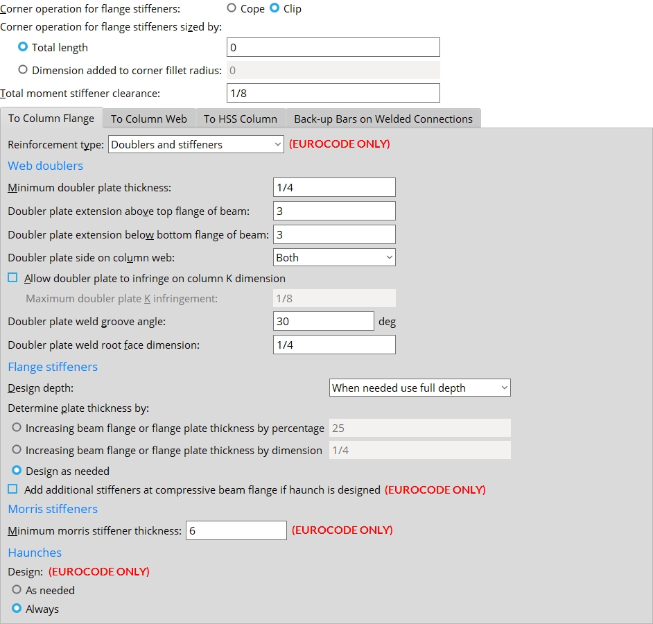
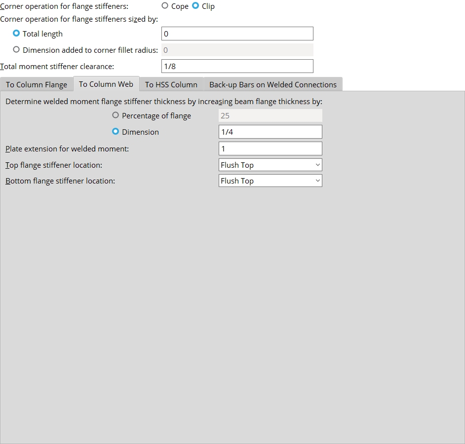
Corner operation for flange stiffeners: Cope or Clip. This applies to moment flange plates (for welded and bolted moment connections to a column web) and to column flange stiffeners (for welded and bolted moment connections to a column flange). It also applies to stability plates.
| moment flange plates | column flange stiffeners | ||
Cope

|
Clip

|
Cope

|
Clip

|
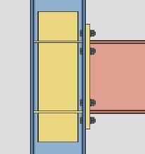
Select Cope if you want a 90 degree cope where the two corners of the moment flange plate or stiffener plate frame to the supporting column web. These corner copes are made so that the plate clears the column's corner fillet radii.
Select Clip if you want a single, 45 degree cut made at each of the corners of the framing edge of the plate. As do corner copes, these corner clips ensure that the plate clears the k distance and k1 distance of the supporting column.
Corner operation for flange stiffeners sized by: ![]() Total length or
Total length or ![]() Dimension added to corner fillet radius.
Dimension added to corner fillet radius.
| tl = total length | da = dimension added |
|
|
The
Total length sizes the cope or clip only if the resulting cut is long enough to clear the k distance and k1 distance. This means, for example, that the default entry of 1/2 inch (or 20 mm) will never be applied to typical column section sizes -- the actual, designed cut will be longer.
The
Total stiffener clearance: A distance. The clearance at each end of a stiffener is 1/2 of the total clearance that is entered here. 0 makes the stiffener flush to the surface. This applies to welded moment stiffener plates (flange plates for welded moments to a column web) and to column Stiffeners for beam moment connections (continuity plates).
A welded moment connection to a column web. The clearance at each end of the stiffener is 1/2 of the Total stiffener clearance that is entered here.
A welded moment connection to a column flange. The clearance shown in this example is 1/2 of the Total stiffener clearance. Also see: Total stiffener clearance on the Plate Design Settings screen provides similar control of clearances on non-moment stiffeners.
To Column Flange
Reinforcement type: Doublers and stiffeners or Morris stiffeners or Doublers only or Stiffeners only or Neither doublers nor stiffeners. These settings apply to fully welded moment connections and moment end plate connections. The default setting here can be overridden on the Beam Edit >  Moment leaf
Doublers and Stiffeners will reinforce the column with web doubler plates and stiffener plates if required by connection design. This will result in a moment end plate without a haunch.
Morris stiffeners will reinforce the column with Morris stiffener plates if required by connection design. This will result in a moment end plate without a haunch.
Doublers only will reinforce the column with web doubler plates if required by connection design. This will result in a moment end plate with a haunch.
Stiffeners only will reinforce the column with stiffeners if required by connection design. This will result in a moment end plate with a haunch.
Neither doublers nor stiffeners will not reinforce the column with additional materials. This will result in a moment end plate with a haunch.
Web doublers
Also see: Connection design applies column web doublers when Design for doublers is selected on the Beam Edit window or in User Defined Connections setup.
Minimum doubler plate thickness: A distance.
Effect on design: Connection design applies column web doubler plates as thick or thicker than the minimum thickness entered here based on analyzing the amount of web shear applied by beams with moment connections framing into column flanges.
Doubler plate extension above top flange of beam: A positive or negative (-) distance.
|
en = distance the doubler plate is extended above the top flange of the beam. |
Enter a positive distance to instruct connection design to extend the doubler plate that distance above the top flange of the beam.
Enter a negative (-) distance to drop the doubler plate that amount below the top flange of the beam.
Doubler plate extension below bottom flange of beam: A positive or negative distance.
|
eb = distance the doubler plate is extended below the bottom flange of the beam. |
Enter a positive distance to instruct connection design to extend the doubler plate that distance below the bottom flange of the beam.
Enter a negative distance to raise the doubler plate that amount above the bottom of the bottom flange.
Doubler plate side on column web: Both or NS or FS. This applies when Column web doubler side is set to Automatic in the![]() Moment leaf on the Beam Edit window or at Home > Project Settings > Job > Connections > User Defined Connections.
Moment leaf on the Beam Edit window or at Home > Project Settings > Job > Connections > User Defined Connections.
|


Both specifies that connection design apply doubler plates on both sides of column webs when doubler plates are required. The thickness of each of these two doubler plates will likely be less than if only one doubler plate were used.
NS instructs connection design to apply a single doubler plate on the near side of the column web. This single doubler plate may be as thick as the combined thicknesses of doubler plates on both sides of the web.
FS configures connection design to apply a single doubler plate on the far side of the column web.
Allow doubler plate to infringe on column K dimension: ![]() or
or ![]() .
.
If this box is checked (
), connection design allows the doubler plate to infringe on the column K dimension.
The Maximum doubler plate K infringement setting is enabled.If the box is not checked (
), connection design will not allow the doubler plate to infringe on the column K dimension. The Maximum doubler plate K infringement setting is disabled.
Maximum doubler plate K infringement: The value set here controls the maximum distance the doubler plate is allowed to infringe on the column K dimension. This setting is enabled when the Allow doubler plate to infringe on column k dimension setting is checked ![]() )
)![]() )
)
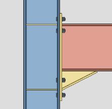
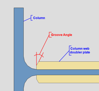
Doubler plate weld groove angle: The value set here controls the degree of angle which the vertical edges of the column web doubler plate are beveled when required. The vertical edges of the plate are beveled and a bevel groove weld is applied when the plate thickness is 3/8" (10mm) or greater. The vertical edges of the plate are not be beveled and a square groove weld is applied when the plate thickness is less than 3/8" (10mm). Also see Doubler plate weld root face dimension.
Doubler plate weld root face dimension: The value set here controls the root face of the vertical edges of the column web doubler plate when beveled edges are required. This only applies when the doubler plate thickness is 3/8" (10mm) or greater. Also see Doubler plate weld groove angle.

Flange stiffeners
Design depth: ![]() As needed or
As needed or ![]() When needed use full depth or
When needed use full depth or ![]() Use full depth at all connections. This applies to any beam moment connection to a column flange that is designed when the box for
Use full depth at all connections. This applies to any beam moment connection to a column flange that is designed when the box for ![]() Design for stiffeners
Design for stiffeners![]() Moment
Moment
|
|
Note: The length of full-depth moment flange stiffeners are the distance between the column flanges minus the Total stiffener clearance that is specified on this screen.
Connection design locks:
Determine plate thickness by: ![]() Increasing beam flange or flange plate thickness by percentage or
Increasing beam flange or flange plate thickness by percentage or ![]() Increasing beam flange or flange plate thickness by dimension or
Increasing beam flange or flange plate thickness by dimension or ![]() Design as needed.
Design as needed.
|
The first two choices set the thickness of flange stiffeners (ts) to be either a percentage increase or a dimension added to the beam's flange thickness (tf). The connection may be a welded moment connection (shown) or a bolted moment connection (not shown). The box for |
Also see: Home > Project Settings > Fabricator > Standard Fabricator Connections > Preferred Connection Material Sizes > Preferred Plate Sizes > Column Stiffeners lets you set the Plate material grade and limit the plate thicknesses that can be applied.
Add additional stiffeners at compressive beam flange if haunch is designed: ![]() or
or ![]() . (UNDER CONSTRUCTION)
. (UNDER CONSTRUCTION)
Morris stiffeners
Minimum Morris stiffener thickness: This applies when the Connection design method is EUROCODE 3 or EUROCODE 3 UK. The minimum thickness applied to the design of Morris stiffener plates.
Haunches
Design: ![]() As needed or
As needed or ![]() For all moment end plates. This applies when the Connection design method is EUROCODE 3 or EUROCODE 3 UK, the Section size of a beam is a wide flange and the Input connection type is End plate or User defined and the Moment type is Bolted.
For all moment end plates. This applies when the Connection design method is EUROCODE 3 or EUROCODE 3 UK, the Section size of a beam is a wide flange and the Input connection type is End plate or User defined and the Moment type is Bolted.
Connection design locks:
To Column Web
Determine welded moment flange stiffener thickness by increasing beam flange thickness by: Percentage of flange or Dimension. This sets the method that used to determine the thickness of the stiffener plates for a welded moment connection on a beam to a column web. Click here for an example from the Connection Guide. Click here for information on connection design locks.
Select Percentage of flange and enter a percentage if you want connection design to create welded moment flange plates that are the beam flange thickness plus the percentage of the flange thickness that is entered here.
Select Dimension and enter a distance if you connection design to apply welded moment flange plates that are the beam flange thickness plus the distance that is entered here.
Note: Beam flange thickness is defined independently for each section size in the local shape file.
Example 1: The flange of a beam whose left end frames to the web of a column is 1 inch thick. You specify a welded moment shear plate connection for the left end of that beam. A Percentage of flange of 25 is entered here. Connection design creates moment flange plates that are 1 1/4 inch thick.
Example 2: The flange of a beam is 1 inch thick. You specify a welded moment shear plate connection for the left end of that beam. A Dimension of 1/4 is entered here. Connection design creates moment flange plates that are 1 1/4 inch thick.
Plate extension for welded moment: The distance that you would like the plate to extend past the flanges of the column. Click here for an example from the Connection Guide. Click here for information on connection design locks.
|
x = the distance the welded moment plate extends beyond the flanges of the column. |
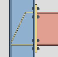
Tapering: Connection design is able to generate a welded moment column web plate that is tapered if the Plate extension ... (x in the above illustration) is greater than 2.5 inches and the flanges of the supported beam are sufficiently narrow. If the width of the beam flange requires a Taper width (tw) that is greater than the overall plate width (pw) minus 1.5 inches (tw > pw - 1.5 inch), connection design generates the plate without a taper.
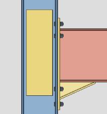
Top flange moment stiffener location: Flush top or Centered or Flush bottom. This sets the placement of the top flange stiffener plate for a beam with a welded moment connection framing to a column web -- click here (Connection Guide) or here (connection design locks) for examples.
Flush top 
Centered 
Flush bottom 
Flush top instructs connection design to place the top surface of the top stiffener in the same plane as the top flange of the beam.
Centered centers the top surface of the top stiffener with respect to the bottom flange of the beam.
Flush bottom places the bottom surface of the top stiffener in the same plane as the bottom surface of the top flange of the beam.
Bottom flange moment stiffener location: Flush top or Centered or Flush bottom. This applies when Welded is selected as the Moment type on a wide flange beam framing perpendicular to a wide flange column web -- click here (Connection Guide) or here (connection design locks) for examples.
Flush top instructs connection design to place the top surface of the bottom stiffener in the same plane as the inside surface of the bottom flange of the beam.
Centered instructs connection design to center the top surface of the bottom stiffener with respect to the bottom flange of the beam.
Flush bottom instructs connection design to place the bottom surface of the bottom stiffener in the same plane as the bottom surface of the bottom flange of the beam.
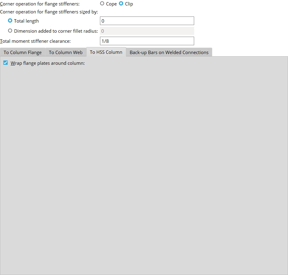
To HSS Column
Wrap flange plates around column: ![]() or
or ![]() . (UNDER CONSTRUCTION)
. (UNDER CONSTRUCTION)
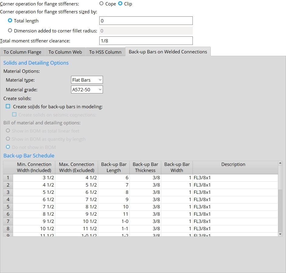
Back-up Bars on Welded Connections
Solids and Detailing Options
Depending on the choices made under this tab, a back-up bar may be shown in the model (after Create Solids) or in the member bill of material (after Detail Members). A back-up bar for a welded moment connection is never shown on the member detail itself, but may be shown in the member's bill of material. To instruct connection design to create a welded moment connection, set the Moment type to Welded.
Material type: Flat Bars or Plates. This applies to welded moment connections. Such connections are designed when the Moment type is set to Welded. A back-up bar may be created for such a connection when ![]() Create solids for back-up bars in modeling
Create solids for back-up bars in modeling
Flat Bars instructs connection design to validate the Back-up Bar Schedule to ensure that all Dimensions entries made to it correspond to entries made to the miscellaneous Preferred Flat Bar Sizes list. This ensures that only flat bars will be used as back-up bars for welded moment connections.
Plates instructs connection design to allow Dimensions entries to the Back-up Bar Schedule to not match entries made to the miscellaneous Preferred Flat Bar Sizes list. Plate material will be used for the welded moment connection back-up bar whenever connection design cannot find a matching flat bar on the Preferred Flat Bar Sizes list.
Material grade: A36 or A572-42 or etc. This sets the steel grade that will be applied to the back-up bar for a welded moment connection. Such connections may be designed when the Moment type is set to Welded. Back-up bars are included with welded moment connections when ![]() Create solids for back-up bars in modeling
Create solids for back-up bars in modeling
Effect on the model: If
Effect on the bill of material: If Home > Project Settings > Fabricator > Bill of Material Layout > Steel grade is specified to be shown in the bill of material and Moment Plate Design Settings > Bill of Material and Detailing Options is set to show the back-up bar in the bill of material, then the Material grade that is selected here will be shown in the Steel Grade column on the member's bill of material.
Create solids for back-up bars in modeling: ![]() or
or ![]() . Regardless of the choice made here, back-up bars will not be shown on the member detail itself.
. Regardless of the choice made here, back-up bars will not be shown on the member detail itself.
|
|
If this box is checked (
leaf) is set to No or possilbly Automatic. Seismic back-up bars will also be generated if is checked. If the box is not checked (
Create solids for seismic connections: ![]() or
or ![]() . Regardless of the choice made here, the back-up bar will not be shown on the member detail.
. Regardless of the choice made here, the back-up bar will not be shown on the member detail.
If this box is checked (
If the box is not checked (
Bill of Material and Detailing Options: Show as total linear feet or Show in BOM as quantity by length or Do not show in BOM. This applies during Detail Members. You need to have back-up bars in the model in order to get them in the bill of material. In order to get back-up bars in the model, ![]() Create solids for back-up bars in modeling
Create solids for back-up bars in modeling
|
|
|
|
|
|
Show as total linear feet results in the two back-up bars for each beam with a welded moment connection being reported as having a Unit Quantity of 1. The Length reported will be the combined length of the two back-up bars. The annotation LIN FT (Imperial) will be added to the Remarks column.
Show in BOM as quantity by length results in the two back-up bars for each beam with a welded moment connection being reported as having a Unit Quantity of 2. The Length reported will be the actual length of one back-up bar. The Minor Mark of the two back-up bars will be listed.
Do not show in BOM results in back-up bars not being shown in the member bill of material.
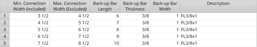
Back-up Bar Schedule
Sets the back-up bar size when ![]() Create solids for back-up bars in modeling is on.
Create solids for back-up bars in modeling is on.
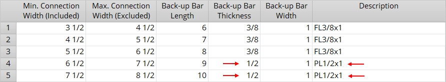
Min. Connection Width (Included): The width that the welded moment connection must be equal to or greater than in order for Create Solids to generate the back-up bar specified on this line.
|
| A welded moment connection with a connection width of exactly 4 1/2 inches would get the back-up bar specified on line 2 since 4 1/2 is excluded from line 1 but included for line 2. |
|
In this example, the field welded moment connection frames perpendicular to a column web, and the connection width is therefore equal to the W section's flange width (bf). For a skewed connection, the connection width would be greater than the beam's flange width since the W section's flange would be cut at an angle instead of square. |
Note: In order for Create Solids to generate a back-up bar,
needs to be turned on.
Max Connection Width (excluded): The width that the welded moment connection must be less than in order to get the back-up bar specified on this line.
|
|
| A welded moment connection with a connection width of exactly 5 1/2 inches would get the back-up bar specified on line 3 since 5 1/2 is excluded from line 2 but included for line 3. |
|
|
The connection width in this example is exactly equal to the length of the field weld along the beam's top flange. |
Length: The length that the back-up bar will be in the model when a welded moment connection undergoes Create Solids with ![]() Create solids for back-up bars in modeling
Create solids for back-up bars in modeling
|
The 3D field weld for the back-up bar is not shown in this example since the display of |
This is the Material length of a flat bar. It is the Order length or Part length for a rectangular plate.
Back-up Bar Thickness: The material thickness of the back-up bar (flat bar or plate).
|
The thickness of a back-up bar corresponds to the Material thickness of a flat bar or the Material thickness of a rectangular plate. |
A flat bar from the miscellaneous Preferred Flat Bar Sizes list will be used for the back-up bar if the thickness and width dimensions match an entry made to the Preferred Flat Bar Sizes list. If the Material type is Plates, connection design will use rectangular plate material if there is not a matching flat bar size.
Back-up Bar Width: The material width of the back-up bar (flat bar or plate).
|
|
The width of a back-up bar corresponds to the Material width of a flat bar or the Material width of a rectangular plate. |
A flat bar from the miscellaneous Preferred Flat Bar Sizes list will be used for the back-up bar if the thickness and width dimensions match an entry made to the Preferred Flat Bar Sizes list. If the Material type is Plates, connection design will use rectangular plate material if there is not a matching flat bar size.
Description: The section size of the flat bar or plate material.
|
| For this example, 1/2 was entered as the Back-up Bar Thickness for lines 4 and 5. Since the Material type was set to Plates and no FL1/2x1 entry had been made to the miscellaneous Preferrred Flat Bar Sizes list, the program automatically entered PL1/2x1 as the Description for lines 4 and 5. |
When the welded moment connection back-up bar is generated, the section size entered here will be filled out as the Description of the material on that material's General Information window. If Bill of Material and Detailing Options is set to show the back-up bar in the member bill of material, then Detail Members applies the entry made here as the Description of the material on the member bill of material.


|
|
OK (or the Enter key) closes this screen and applies the settings.
Cancel (or the Esc key) closes this screen without saving any changes.
Reset undoes all changes made to this screen since you first opened it. The screen remains open.
- Red or yellow exclamation point icons
 or
or 
- Validation: If you switched the Material type for back-up bars from Plates to Flat Bars, the Back-up Bar Schedule will be checked for invalid entries to its Back-up Bar Thickness and Back-up Bar Width fields. If invalid entries are found, you will not be permitted to exit this screen until those entries are fixed or you switch to Plates as the Material type.
- If you want changes to this window applied to particular members, you can Process Selected Members then Process and Create Solids. Or you can Mark Members for Processing then Process and Create Solids.

